


How to read an aeronautical navigation chart?
Categories :
Aeronautical navigation chart
, BAYO
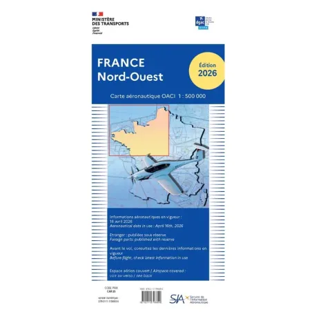
With spring comes the season of newly updated aeronautical charts. Pilots can now find them in our online store.
If you are not yet a pilot, if you dream of becoming one, or if you are preparing for training to obtain your license, this is the perfect opportunity to familiarize yourself with this essential tool.
Wondering how to read an aeronautical chart? To get started, here are the essentials in 10 key points.
1. The Map Background
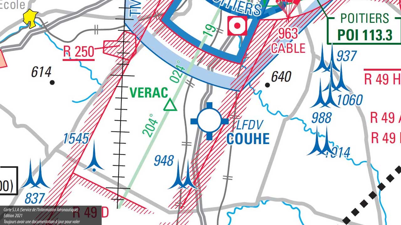 It looks like a road map or a topographic map. However, it particularly highlights elevated landscape elements: natural obstacles, wind turbines, power lines, pylons, etc.
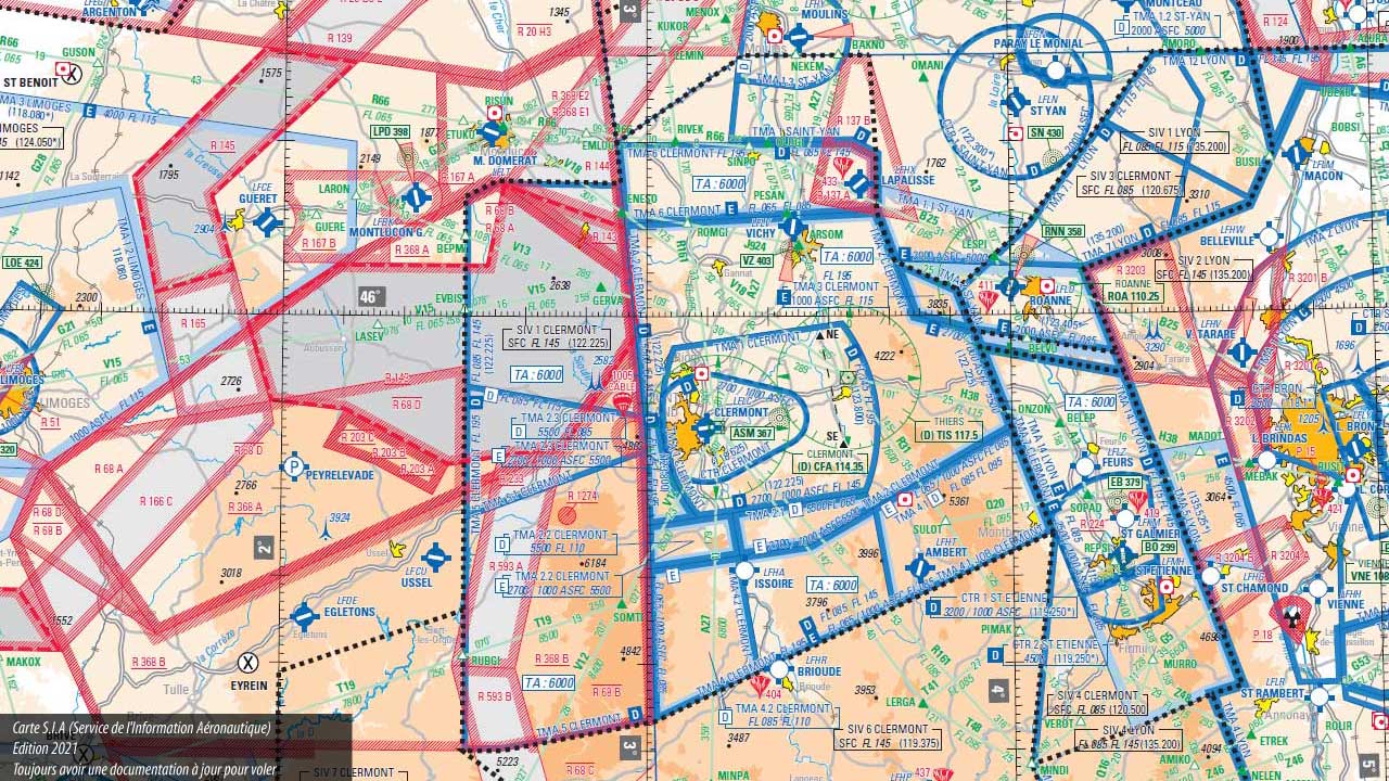
Legend: In this map excerpt, you can spot several obstacles south of Poitiers, represented by small blue pyramids accompanied by their height above the ground.
2. Navigation Zones on an Aeronautical Chart
 Airspace is divided into different types of zones. The first to know is for information, alert, and control services. From this perspective, mainland France is divided into five major zones called FIRs (Flight Information Regions): the FIRs of Bordeaux, Brest, Marseille, Paris, and Reims.
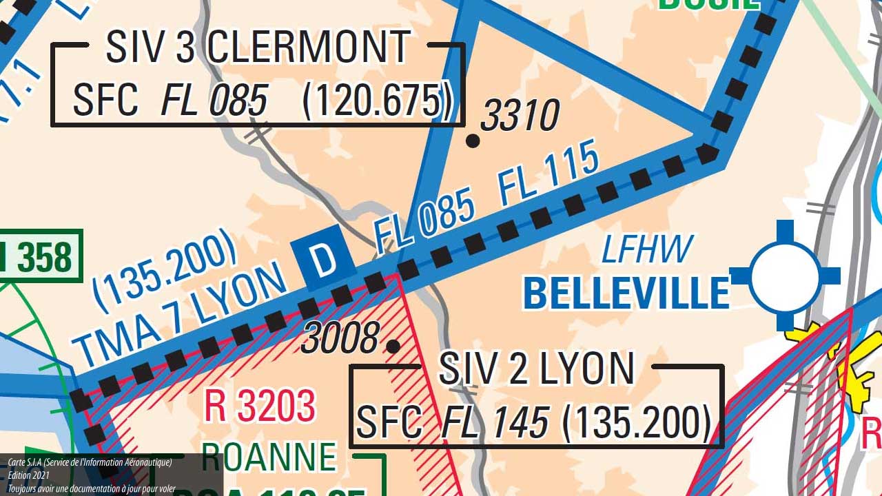
Each of these zones is further divided into SIVs (Flight Information Sectors), linked to an airport that provides the service.
Legend: In this example, the black boxes distinguish portions of airspace associated with the SIVs of Lyon and Clermont, with the boundary between the two sectors represented by black dotted lines.
 Additionally, within the same airspace, zones are differentiated based on the regulations that apply to them. These zones are easily identifiable on maps: they are outlined by thick blue or red lines.
Unlike road traffic routes, which are defined in two dimensions on a road map, air zones are volumes, meaning they are defined in three dimensions. The two horizontal dimensions of the zone are represented by these thick red or blue lines.
The vertical limits of the zone, along with other information, are indicated in the same color as the boundary lines—either along the lines themselves or gathered in a box. We now need to zoom in to decipher these details.
3. Zone Characteristics
Each zone on an aeronautical chart is characterized by its class, type, ceiling, and floor.
These indications are present on all aeronautical charts, but their presentation varies from one chart to another. Therefore, it is essential to refer to the legend to accurately interpret the information on the map.
For our examples, we use charts from the Aeronautical Information Service (SIA), but you can also find IGN charts, Air Million charts, or CartaBossy charts in our e-store. While their presentation varies slightly, the information remains the same.
Let's break them down...
4. Airspace Class
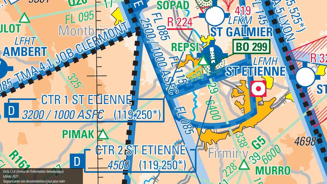 The class is indicated by a single letter, clearly visible within the zone or on the left side of the information box. The class determines the rules to follow within the zone, such as the requirement for radio contact or who can access the zone, particularly distinguishing between Visual Flight Rules (VFR) and Instrument Flight Rules (IFR).
The different classes are designated by the letters A, B, C, D, and E for controlled zones, and G for uncontrolled zones.
Legend: In the example above, you can see that the two zones identified in the blue boxes are Class D zones.
5. Type of Airspace
 The type of airspace indicates the purpose of the zone and is designated by three letters, followed by the name of the relevant area. There are three types of zones where you can fly your aircraft... provided you follow the rules associated with the zone's class:
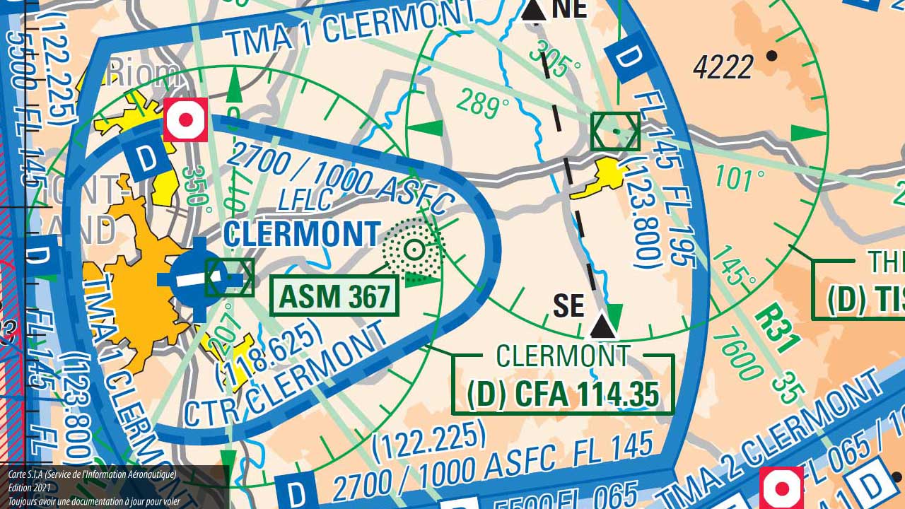
- CTR (Control Traffic Region): The airport traffic zone, directly above and around the airport. This is where aircraft take off and land. Logically, a CTR zone extends to the ground.
- TMA (Terminal Maneuvering Area): The space above and surrounding the CTR; it serves as the airport's approach area.
Legend: Here, we have a smaller zone representing the CTR of Clermont-Ferrand Airport, surrounded by a larger zone, the TMA1. Their characteristics are noted along the boundary lines. A second, broader approach zone is visible.
6. Special Airspace Zones
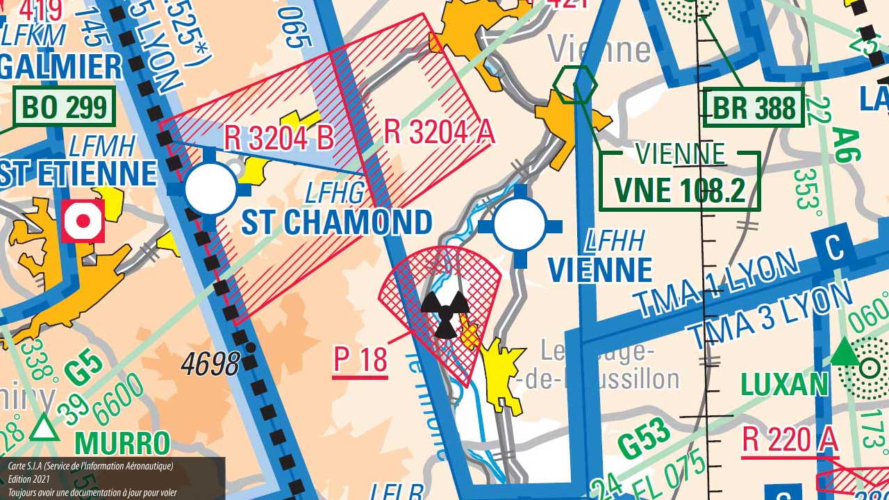 Some zones (in red on the charts) do not fit the above classifications: these are prohibited or conditionally accessible zones. They correspond to military installations, nuclear plants, or hazardous areas, etc. These zones are designated by the letters P, ZIT, R, D, or ZRT.
Also noteworthy: RTBA zones, which are very low-altitude military flight corridors, also shown in red on the maps.
Legend: Here, you can see a prohibited zone (red hatched outline) above a nuclear power plant and a dangerous zone (red dashed outline), the R3204 between Saint-Etienne and Vienne.
7. Vertical Limits of Zones
The indications for each zone also provide information about its third dimension, which the map cannot physically depict: the vertical dimension. These two figures are either on the same line or stacked, separated by a horizontal line. They indicate the floor and ceiling of the zone. The regulated space lies between these two altitudes or heights.
If only one number is given, the zone extends to the ground—this is specifically the case for CTR zones.
8-10. More Details...
[Further translations following the same pattern...]
Share this content
Add a comment